
Use of non-metallic reinforcement for concretes in aggressive environments
To obviate the phenomena of splitting of the concrete cover, which self-sustain the phenomenon of deterioration, stainless steel reinforcements are used with an increase in costs and greater expenses related to strengthening of the bending areas, of the weldings, etc.
ABSTRACT: In highly aggressive environments, reinforced concrete has a very limited duration. The reason is substantially linked to the practical difficulty of producing and maintaining concrete without faults. To obviate the phenomena of splitting of the concrete cover, which self-sustain the phenomenon of deterioration, stainless steel reinforcements are used with an increase in costs and greater expenses related to strengthening of the bending areas, of the weldings, etc. Recently, the composite materials industry has provided reinforcement cages which are very similar to traditional steel but made of inert materials resistant to the attacks of aggressive environments. This document contains an actual case of intervention performed in certain tanks for the collection of industrial waters where, after approximately 40 years of activity, the internal steel reinforcements were profoundly attacked by corrosion. Experimental bending tests of steel - FRP comparison show significant differences in behaviour of this new type of concrete.
Use of non-metallic reinforcement for concretes in aggressive environments
Marco Arduini1, Andrea Nicoletti2
1 Coforce, Reggio Emilia, Italy 2 Basf CC Italia Spa, Treviso, Italy
1.GENERAL INSTRUCTIONS
At the start of the 21st century the application offibreglass reinforcements began for the creation ofreinforced concrete diaphragms. The choice to usethis material in place of traditional steel wasessentially due to the need to create sections ofretaining wall that could be easily crossed by theboring machine.
By exploiting this field of application, numerous areas of experimental research began with the aim of understanding the durability of the GFRP system and the long-term behaviour.
The studies carried out led to the development of calculation codes (ACI440, CNR DT203) and experimental procedures for characterisation (ASTM D7957). Thanks to this panorama the creation of concretes with FRP reinforcement has become a further possibility for the designer as well as the design of concrete reinforced with steel bars. North America has a leading position in the dissemination and use of this new building material. In Europe the regulatory aspect has not yet been completely resolved. The factors that allow a system to be used within the European common market are:
- International regulations for design ofrecognised validity
- Harmonised procedures for obtaining ECproduct certification
- Verification of an adequate safety factor
In Europe there are currently two documents that are useful for the design:
- CNR DT 203 is a document (Italian/English)that was drafted in 2006 by a commission ofexperts for design according to the latest limitstate method. It also contains rules andprocedures for product certification and for siteacceptance procedures.
- CEB-FIP Bulletin 30 is a document prepared bya commission of experts at European levelcontaining useful data for design
In the above-mentioned design document, the procedure for the design follows the same logic as for traditional reinforced concrete: preservation of the flat sections and the perfect concrete - reinforcement adherence. Because of the constitutive properties of FRP reinforcement and the need to contain the costs of materials, the bars for reinforced concrete that currently seem to have greater penetration on the market are those based on glass yarns which we will now identify with the initials GFRP.
To verify the precision of the calculation method, an experimental bending test program was carried out on slabs and beams made of concretes with different mechanical characteristics.
In this document, the results of 6 slabs of true concrete dimension are presented with bars of different shape ratio ϕs. defined as: Bar area/bar perimeter; other tests are still underway with concretes of different mechanical properties.
The value of ϕs is important because it is economically more convenient to produce large diameter bars but as the diameter of the GFRP bars increases two disadvantageous situations occur:
- The tensile strength decreases (despite having the same percentage of wire inside)
- The bar - GFRP interface tensions increase with the consequent appearance of slip phenomena that increase the arrow and opening of faults
Unfortunately, the ACI 440, CNR DT 204 and CEB FIP 30 regulations do not impose limits on the maximum diameter of the reinforcements and minimum distance between rods, it is therefore important to check these parameters and propose some revisions if are necessary.
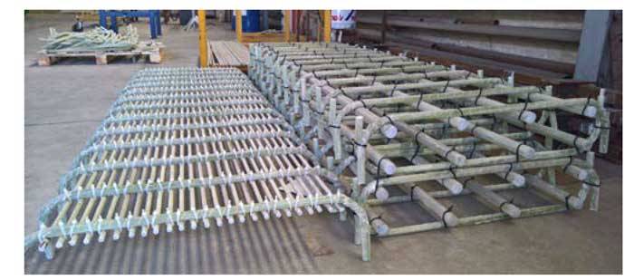
Fig. 1 - Reinforcement cages ready for casting
2. EXPERIMENTAL PROGRAM
3 pairs of reinforcement cages were created:
- Cage 1: consisting of 25 GFRP bars, nominal diameter 12 mm above and below (overall area in taut zone: 2800 mm2 and shape ratio: area/contact perimeter ratio ϕs= 3)
- Cage 2: consisting of 4 bundles of 4 GFRP bars, nominal diameter 16 mm above and below (overall area in taut zone: 3200 mm2 and shape ratio: area/contact perimeter ratio ϕs= 5)
- Cage 3: consisting of 4 GFRP bars, nominal diameter 32 mm above and below (overall area in taut zone: 3215 mm2 and shape ratio: area/contact perimeter ratio ϕs= 8)
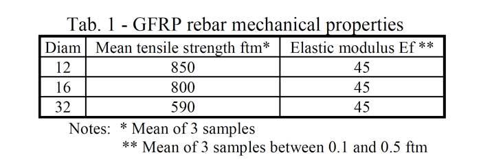
GFRP bars were left exposed to the external environment for approximately 3 years. The mechanical properties of the welded reinforcements are reported in Tab. 1.
Two types of bending test were performed:
- Bending "B": using the configuration of Fig. 2 a
- Shear "S": using the configuration of Fig. 2 b
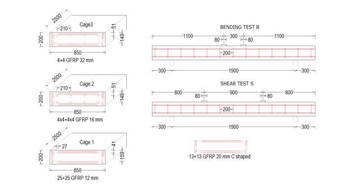
Fig. 2 - Test configurations: (a) Bending test B, (b) Shear test S (dimensions in mm)
The casts were performed simultaneously with the same mixture of cement, sand and aggregates (maximum diameter 20mm). The casts were left to cure for approximately 40 days before performing of the tests. The day before the tests, non-destructive testing was carried out using the SONREB method (hammer test + ultrasonic test).
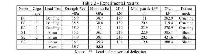
Four positions were investigated for each plate and the Leo Pascale regression formula [1] was used. The estimate of the compressive cubic characteristic strength Rc and of the dynamic elastic modulus Ec (assuming the standard density of 2300kg/m3 and the Poisson coefficient v=0.15) are reported in Tab. 2. Compared to the mean result, the slabs shown a minimum difference of +-1 MPa on the strength value.
The test was conducted monotonically, with only one initial settling cycle of up to about 10% of the ultimate tensile strength. During the test the following were acquired:
- - the applied load 2F
- - the mid-span deflection
- - deformation of the concrete at the extrados in the centre of the slab by means of LVDT on a measuring base of approximately 20cm
Before reaching the breaking point, after having exceeded the design limits and having defined the formation of the crisis mechanism, the measuring instruments of the displacements and deformations were removed. T
he maximum load reached at Fmax break is, therefore, slightly higher than that recorded continuously and is shown in Tab. 1. The load-arrow behaviours are shown in Fig. 3, while the load-deformation behaviour in the compressed area is shown in Fig. 4.
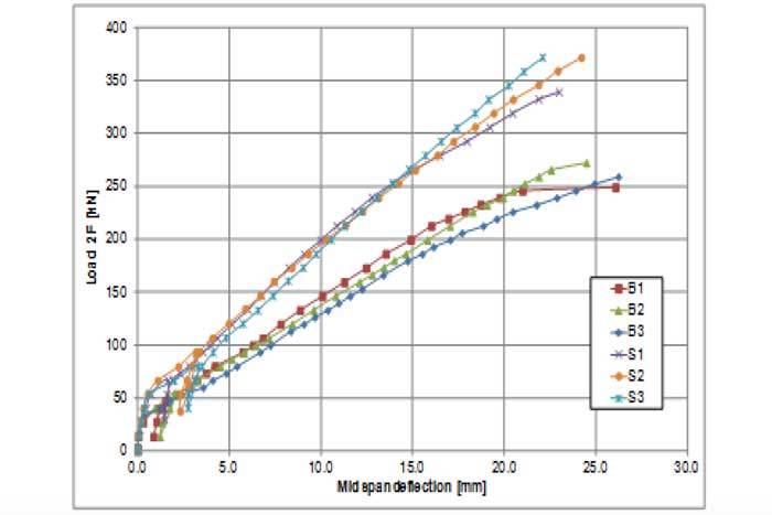
Fig. 3 – Total load - arrow in centre line until the moment the instruments have been removed
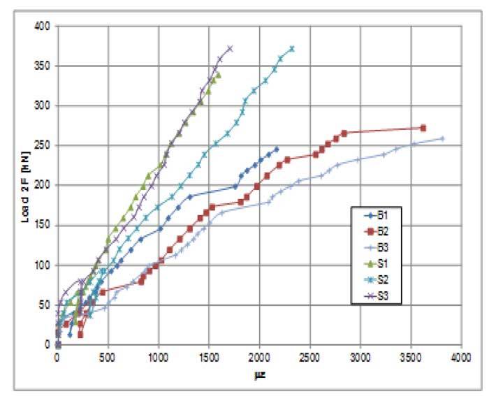
Fig. 4 – Total load - deformation of the concrete at the extrados in L/2 up to the moment in which the instruments have been removed
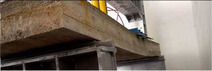
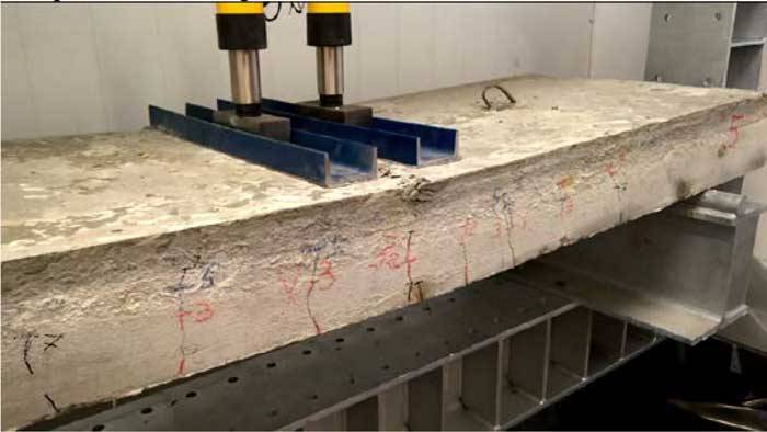
The failure modes obtained are essentially due to concrete crushing, some images are presented in Fig. 5.
Sample B1: breaking mode
Sample B2: breaking mode
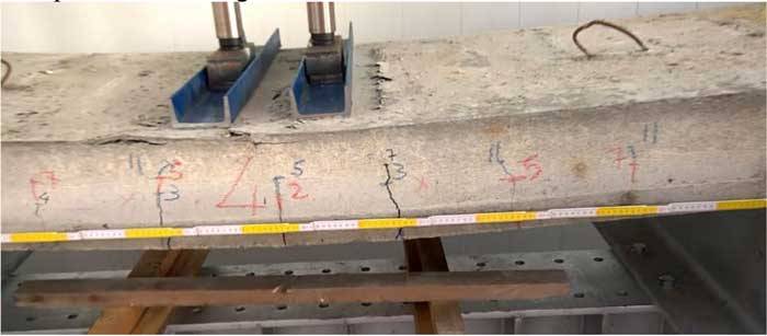
Sample B3: breaking mode
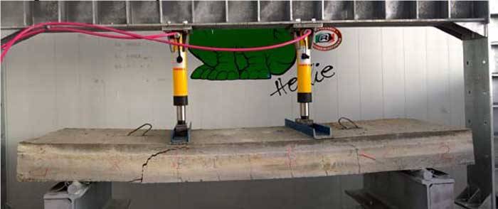
Sample S1, breaking mode
...
L'ARTICOLO COMPLETO E' DISPONIBILE IN ALLEGATO
KEYWORDS: Field applications and case studies, Experimental study, FRP internal reinforcement, Bond and interfacial stresses, GFRP, Reinforced concrete.
Articolo presentato in occasione degli Italian Concrete Days 2018 di aicap e CTE

Dal 14 aprile al 17 aprile 2021 si terrà la terza edizione degli Italian Concrete Days. Ulteriore informazione sull'evento a questo LINK.